A data hall, inside a container.
Power, cooling, fire, security and DCIM built into an ISO container, witness-tested as one unit, shipped, and craned onto your pad. You bring the rack count and density. We bring a hall that powers on.
Six subsystems, factory-married inside one container.
No general contractor stitching trades together on your site. White space, power, cooling, fire, security and monitoring arrive pre-coordinated and pre-tested inside the container, documented as a single line of responsibility.
 01 White space
IT white space, inside the container
A sealed, pressure-balanced contained aisle the length of the container. Cable management, busway and rack PDU layout fixed at design freeze.
Integrated power train
Grid interface to rack PDU as one tested block: MV switchgear, transformer, LV distribution, modular UPS and storage. Delivered by our Power Train Unit line.
See the Power Train Unit →Precision cooling
Sized to total heat load with N+1 redundancy. Perimeter DX, in-row CRAH, rear-door heat exchangers or direct-to-chip liquid, matched to your rack density.
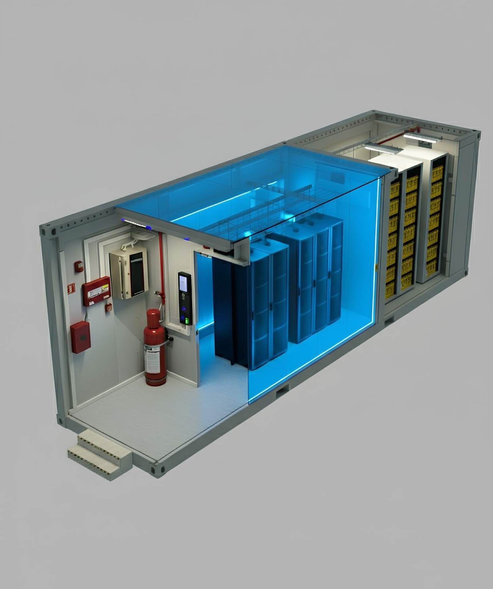
Detection & suppression
VESDA aspirating smoke detection with NOVEC 1230 or IG-55 clean-agent release. No water near the racks.
Physical security
Mantrap entry, biometric and card access, internal and external CCTV, intrusion zones logged to the DCIM.
 Anatomy
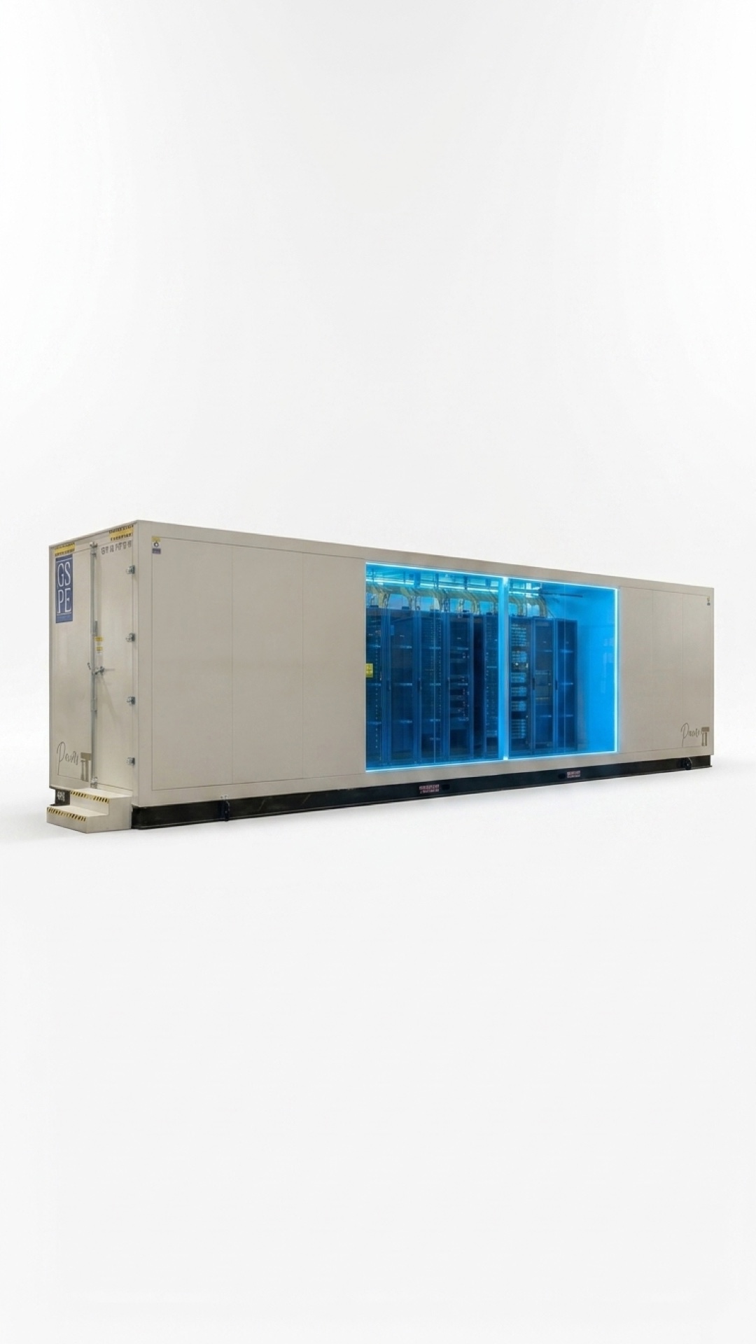
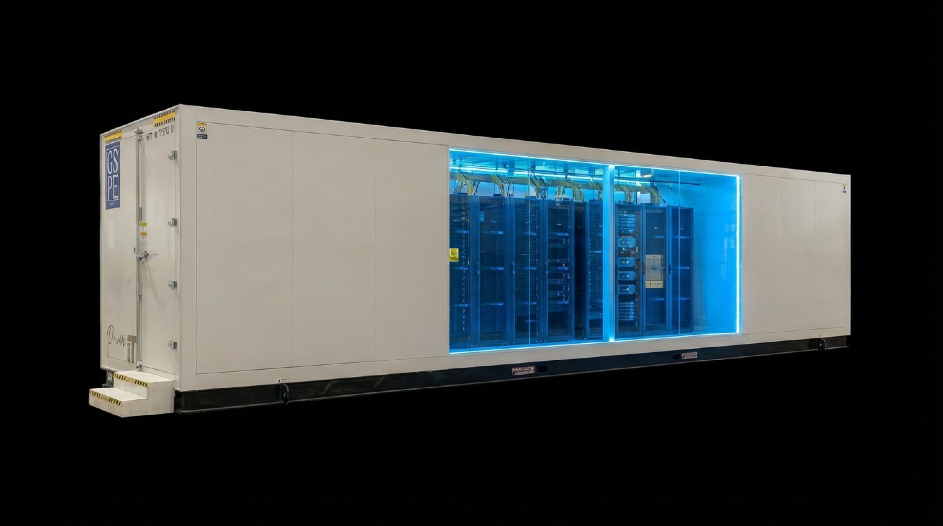
Open the side, see the hall
Racks, walkway and plenum, all inside the ISO shell, exactly as tested on the floor.
 06 Monitoring
Monitoring & DCIM
One pane of glass. Power, thermal, fire and access on open protocols, ready for your BMS.
One ISO container. A whole data hall inside.
Racks, power, cooling and a walkway, engineered into a single standard footprint. What you crane onto the pad is exactly what we tested on the floor.
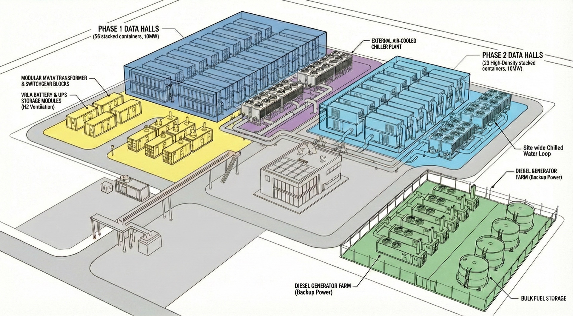
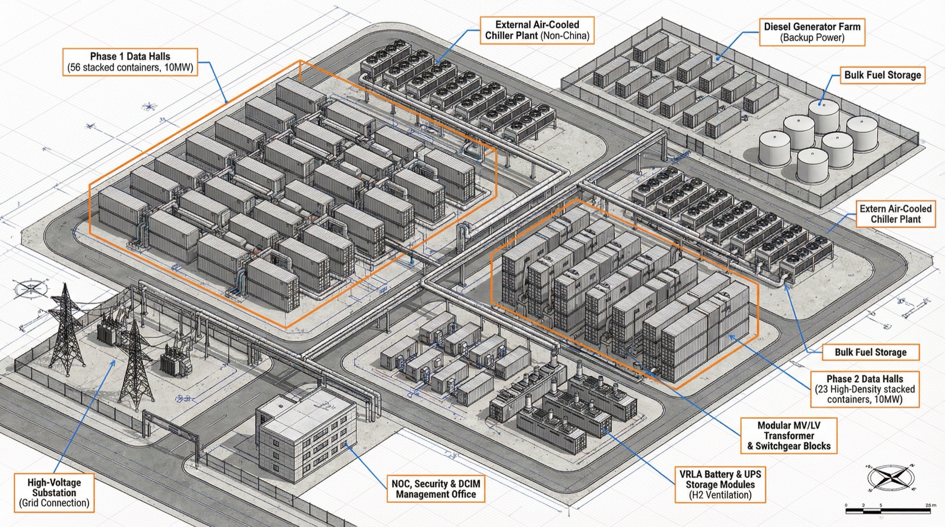
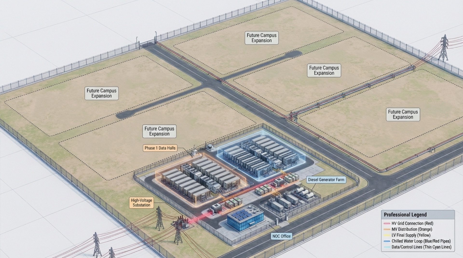
Start at one container. Grow to a campus.
A shared central plant feeds independent containers. Add units to the pad as load arrives, without re-engineering what already runs.
Edge container
A single contained row for edge and far-edge sites. Self-cooled, self-monitored, relocatable.
Data hall container
A full hall of contained racks with dedicated power and cooling, the core building block.
Multi-container campus
Containers on a shared central plant, phased to demand.
live across one DCIMCooling chosen by density, not by habit.
Four cooling architectures, picked against your actual kW per rack. Mix them across containers on the same pad.
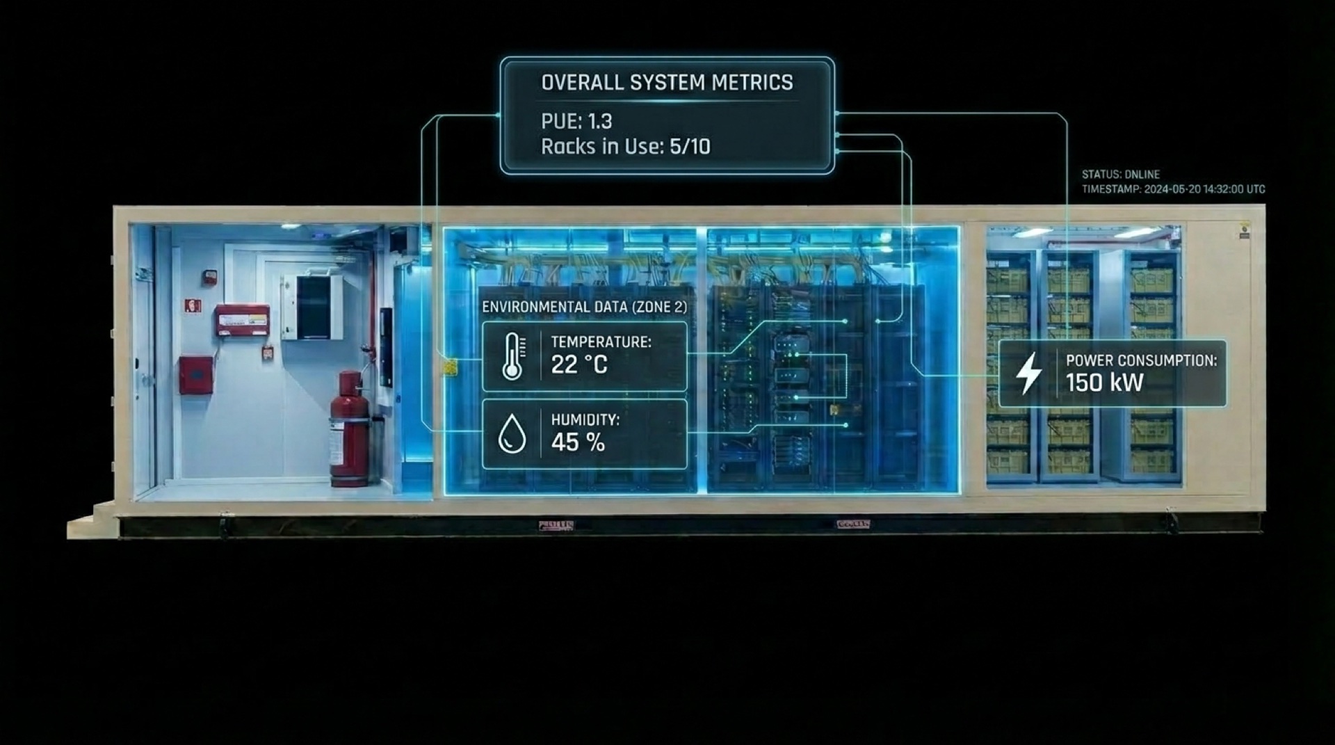
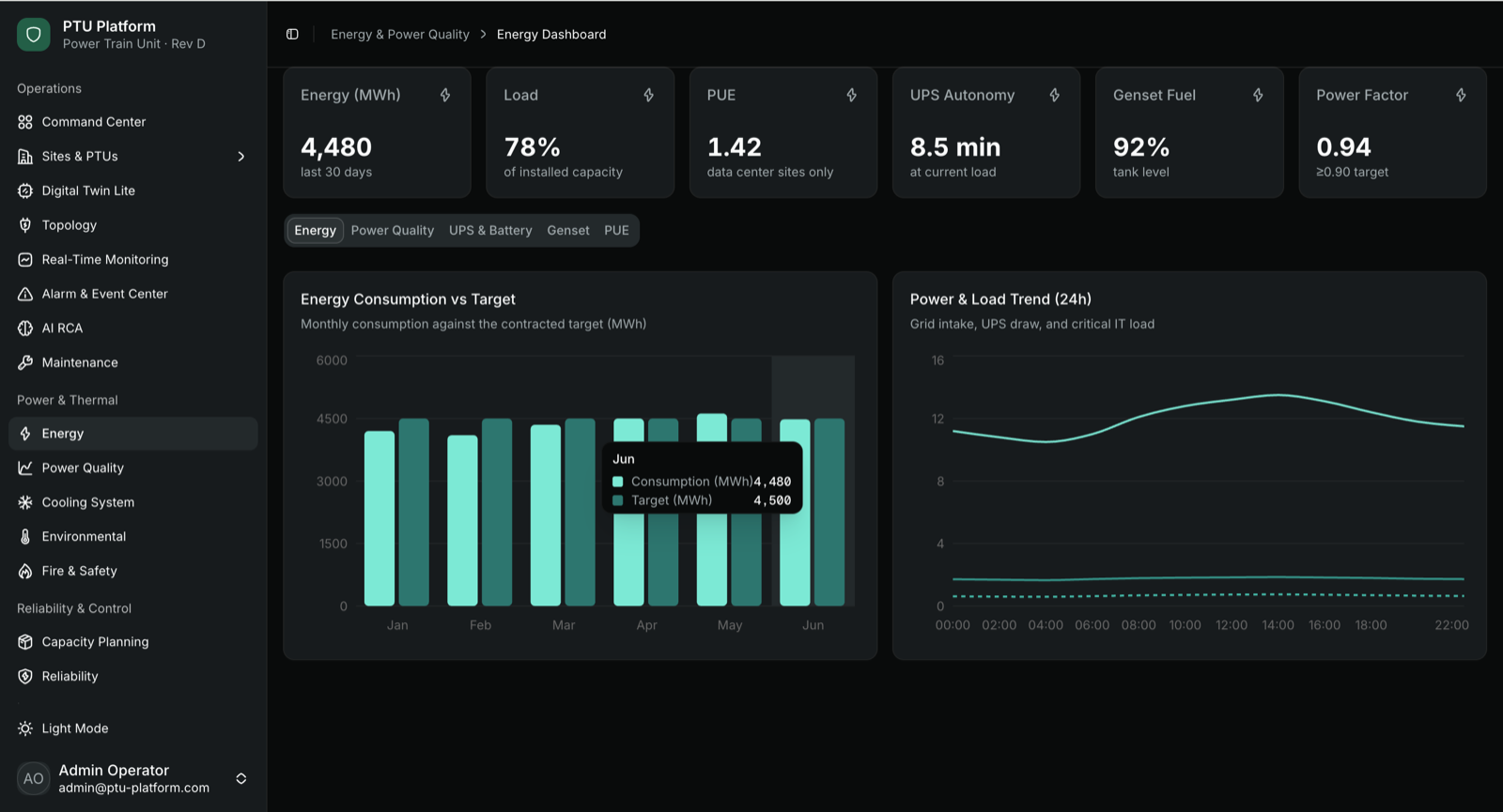
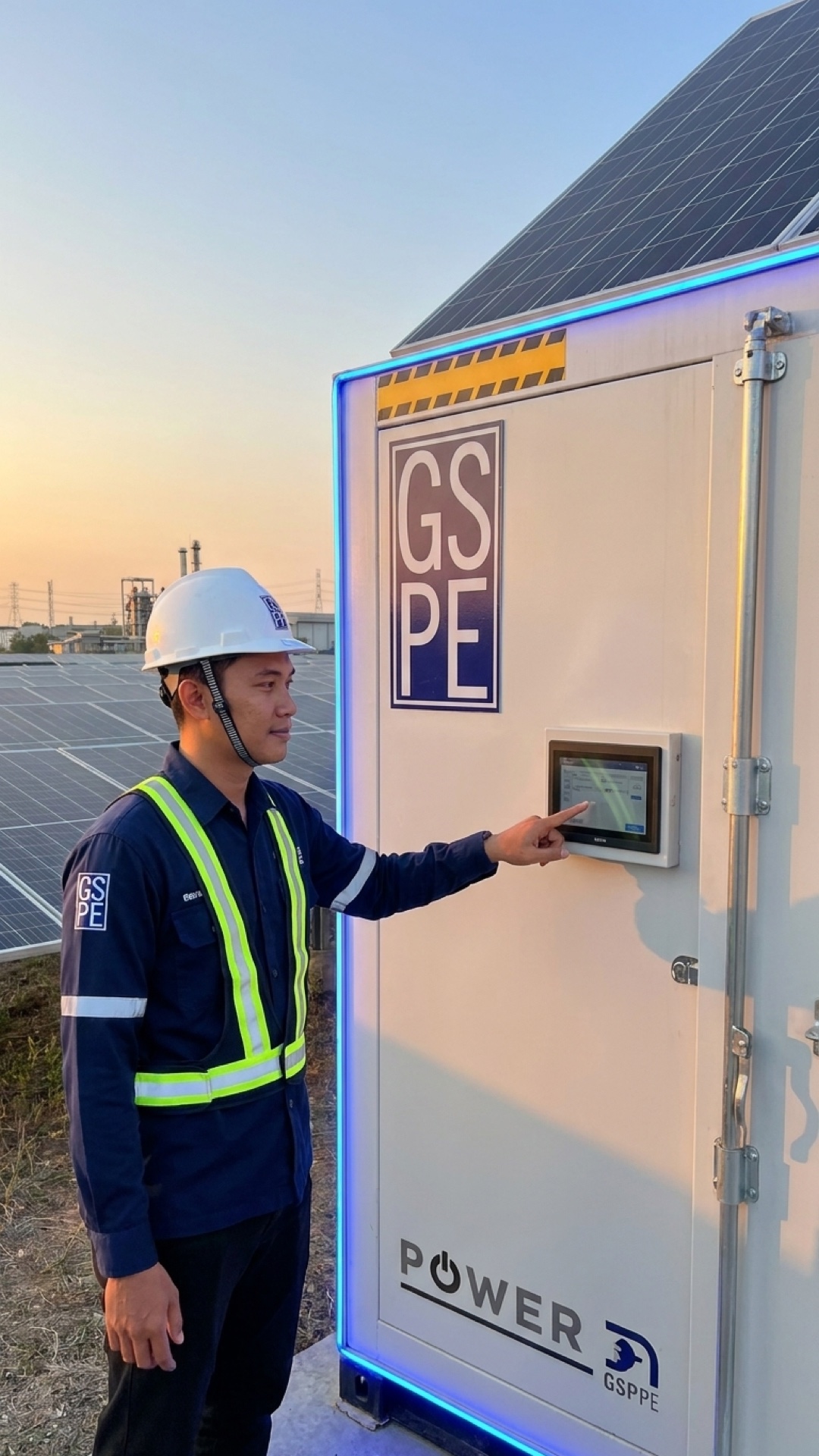
Power, thermal and capacity, watched around the clock.
Every container streams its own telemetry and camera feeds into one console. Power draw, inlet temperatures, fire zones and door state are logged continuously, so capacity and faults are visible the moment they move.
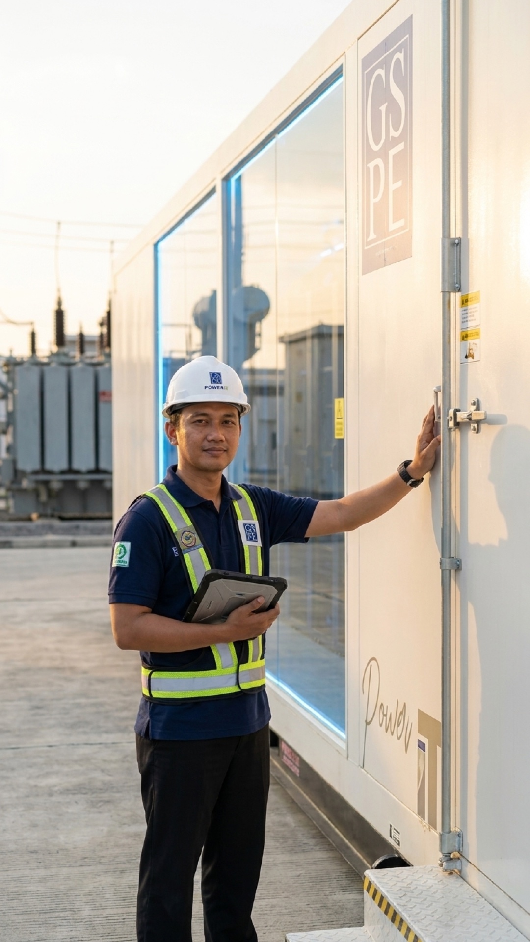
Integrated in our factory. Proven before it ships.
Trades that usually collide on a live site are coordinated under one roof, inside the container. You witness the unit run on the floor before it is sealed, shipped, and craned onto your pad.
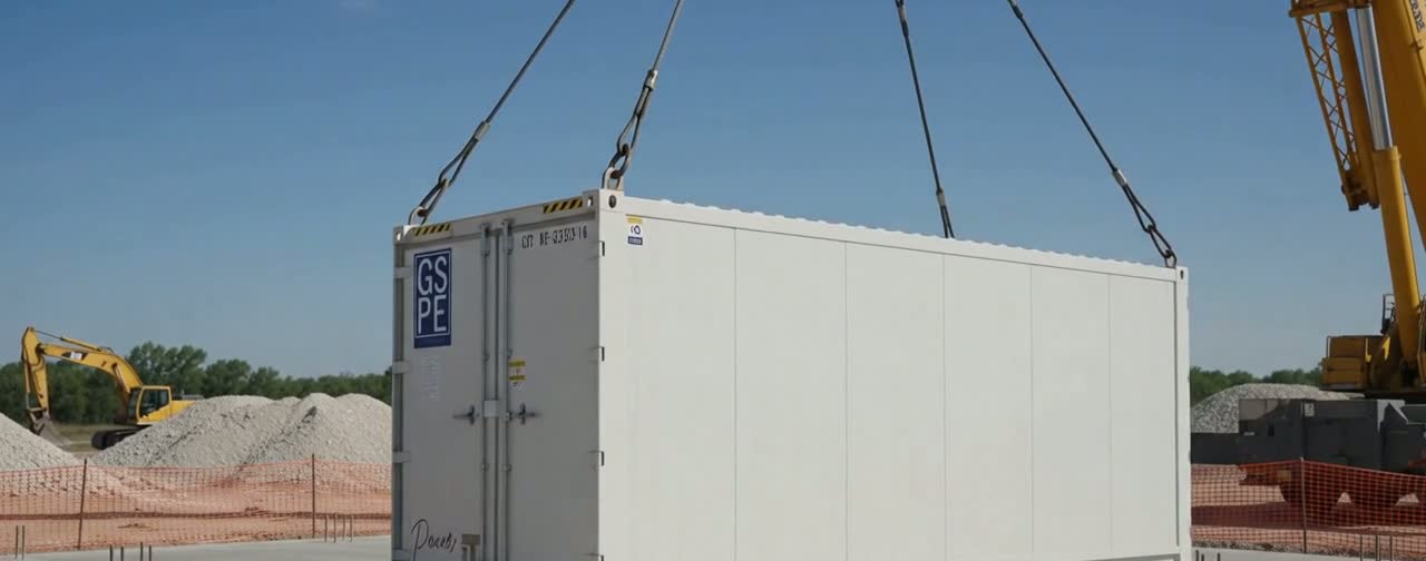
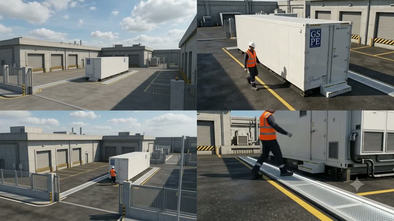
Craned onto the pad, powered on, handed over.
What we test on the factory floor is what lands on your site. One sealed container, one walk-around, one set of as-builts, ready to energize.
Resilience configured to the load that matters.
Pick the redundancy level per container and map it to the rating your stakeholders already speak.
Single path
Exactly the capacity the load needs, no concurrent maintenance margin. For dev, edge, and workloads that tolerate a maintenance window.
Concurrently maintainable
One redundant component per system, so any single unit can be serviced without dropping the load. The common production choice.
Fault tolerant
Fully duplicated, independent power and cooling paths. A failure on one path never reaches the IT load. For mission-critical containers.
Bring your rack count and density.
Tell us the load, the resilience target and the site. We will scope the containers, the cooling and the schedule to power-on.